|
Vine Antennas UK HAM Radio Amateur Radio Accessories Antennas ATU's https://www.vine-comms.co.uk/product/vine-antenna-du-1500t-diff/  |
Vine Antenna DU-1500T Differential | LAMCO Barnsley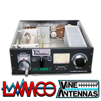
Price: £599.95 SKU: LAMCO DU-1500T Differential ATU Product Categories: VINE ANTENNAS ANTENNA TUNERS Product Tags: DU-1500T, LAMCO DU-1500T Differential ATU 1.5Kw, Vine Antenna DU-1500T Differential ATU 1.5Kw LAMCO Barnsley Product Page: https://www.vine-comms.co.uk/product/vine-antenna-du-1500t-diff/
Product Summary
Product DescriptionVine Antenna DU-1500T Differential ATU 1.5KwVine Antenna DU-1500T Differential ATU 1.5Kw LAMCO Barnsley
FEATURES The DU 1500T optimizes the performance of your antenna and transmitter or SWL receiver by providing adjustable impedance matching. The DU1500T also measures the Power and Standing Wave Ratio (SWR), which allows you to tune the indicted SWR to the lowest possible ratio for the selected transmit frequency.
SPECIFICATIONS
FRONT PANEL INDICATORS AND CONTROLS
Meter..............................Cross needle Power and SWR meter. CONTROLS Input Tuning......................Continuous rotation 4,5kV capacitor 330pF Antenna Tuning..................Continuous rotation 4,5kV capacitor 330pF Antenna Switch Selector.........Five position ceramic switch: COAX 1, Tuned and COAX 2 Tuned and BYPASS, COAX 1 DIRECT, COAX 2 DIRECT Power Range Switch..............Two position: 200W/2kW Warning: !! on 1.8MHz for SWR worse then 1:3 MAX 800W!! REAR PANEL CONNECTORS Coax 1.................................SO-239 Teflon connector Coax 2.................................SO-239 Teflon connector Balanced Line........................Dual high voltage ceramic terminal Include 4:1 balun OTHER Frequency Coverage..................1.8-30MHz ,continuously tunable Power Maximum.....................1500W max 2kW Input impedance......................50 ohm Output impedance.....................25-600ohm and wire 2000ohm Dimension...... ........................H 4.7” (12cm) W 13” (33cm) x D 13” (33cm) Weight..................................10 lbs. (4.5kg)
CONTROL/CONNECTORS
FRONT PANEL FUNCTIONS
Continuously adjustable output capacitor.
Five-position rotary switch an output coaxial connector. 1.TUNED COAX 1 selects the COAX 1connector trough the impedace matching circuit. 2.TUNED COAX 2 selects the COAX 2 connector trough the impedance matching circuit. 3.DIRECT BYPASS selects BYPASS COAX connector bypassing the impedance matching circuit but provindingSWR, FORWARD, and REFLECTED power meter readings. 4.DIRECT COAX 1 select the COAX 1 connector bypassing the impedance matching circuit but providing SWR, FORWARD, and REFLECTED meter readings. 5.DIRECT COAX 2 selects the COAX 2 connector bypassing the impedance matching circuit but providing SWR, FORWARD, and REFLECTED meter readings.
5.RANGE SWITCH Two-position switch selects the range (200W or 2kW) of FORWARD and REFLECTED Power displayed on the power meter. When the METER (power range) switch 200W the FORWARD meter Scale reads 200W full scale and the REFLECTED meter scale reads 40W full scale.
When the METER switch is on 2kW, the FORWARD meter scale reads 2kW full scale and the REFLECTED meters scale reads 400W full scale. REAR PANEL CONNECTORS
DU1500T Rear Panel
2 COAX 1 - Coaxial connector for output to Antenna One.
6 BALANCED OUTPUT Two ceramic post for output to RF balanced twin-lead antennas.
INSTALLATION Select a location for the DU 1500T that allows the connectors to be free of any possible
Contact during operation.
WARNING:SOME BALANCED OR END-FED ANTENNAS WILL PRODUCE HIGH RF VOLTAGES AT THE BANANA CONNECTORS.RF BURNS MAY RESULT IF TOUCHED DURING TRANSMISSION.
INSTALLATION PROCEDURES
the transmitter or trough the tuned circuit depending ont he setting of the OUTPUT SELECTOR switch ont he front panel. 3If you are using a balanced feed antenna,connect the INSTALLJUMPER in the COAX 1 connector and switch band switch TUNED COAX 1.
PUT SELECTOR switch. Any antenna that does not require the use o fan antenna tuner may be connected to the BYPASS connector, if desired.
BEFORE OPERATION
WARNING: DO NOT OPERATE THE DU 1500T WITH THE COVER OFF!
TUNING
the suggested settings before applying transmitter power. Actual settings may vary from antenna to antenna.
If your transmitter has a TUNE position, select that position.
WARNING: DO NOT EXCEED 1500 WATTS PEP (SINGLE TONE) .
transmitter power control.
8 until the lowest SWR reading is obtained. The SWR should be 2:1 or lower.
NOTE:This procedure takes patience the first time. The INPUT and OUTPUT Controls vary the capacitors and provide fine adjustments. https://www.hamradio-shop.co.uk/product/vine-antenna-rs-hf-osf-20/ https://www.hamradio-shop.co.uk/product/vine-antenna-rs-hf-osf-80/
Product Gallery 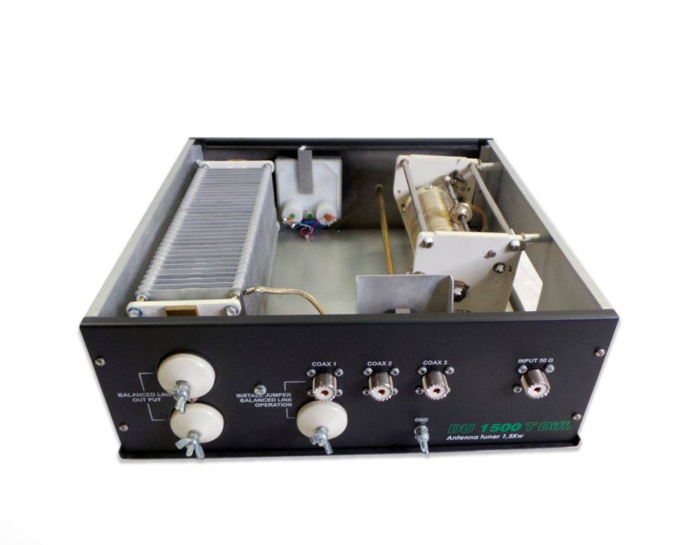 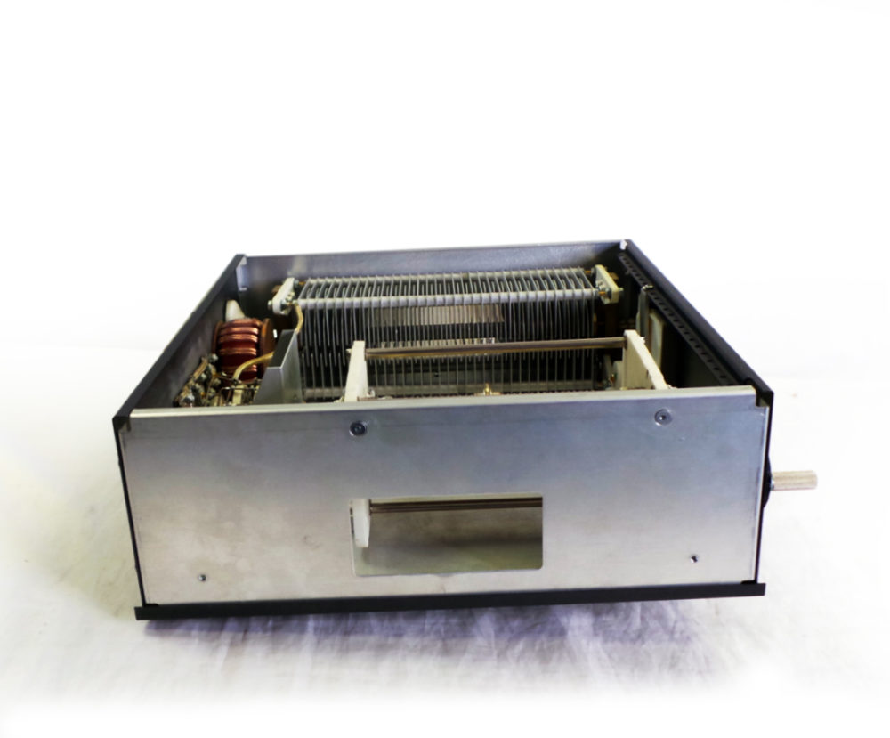 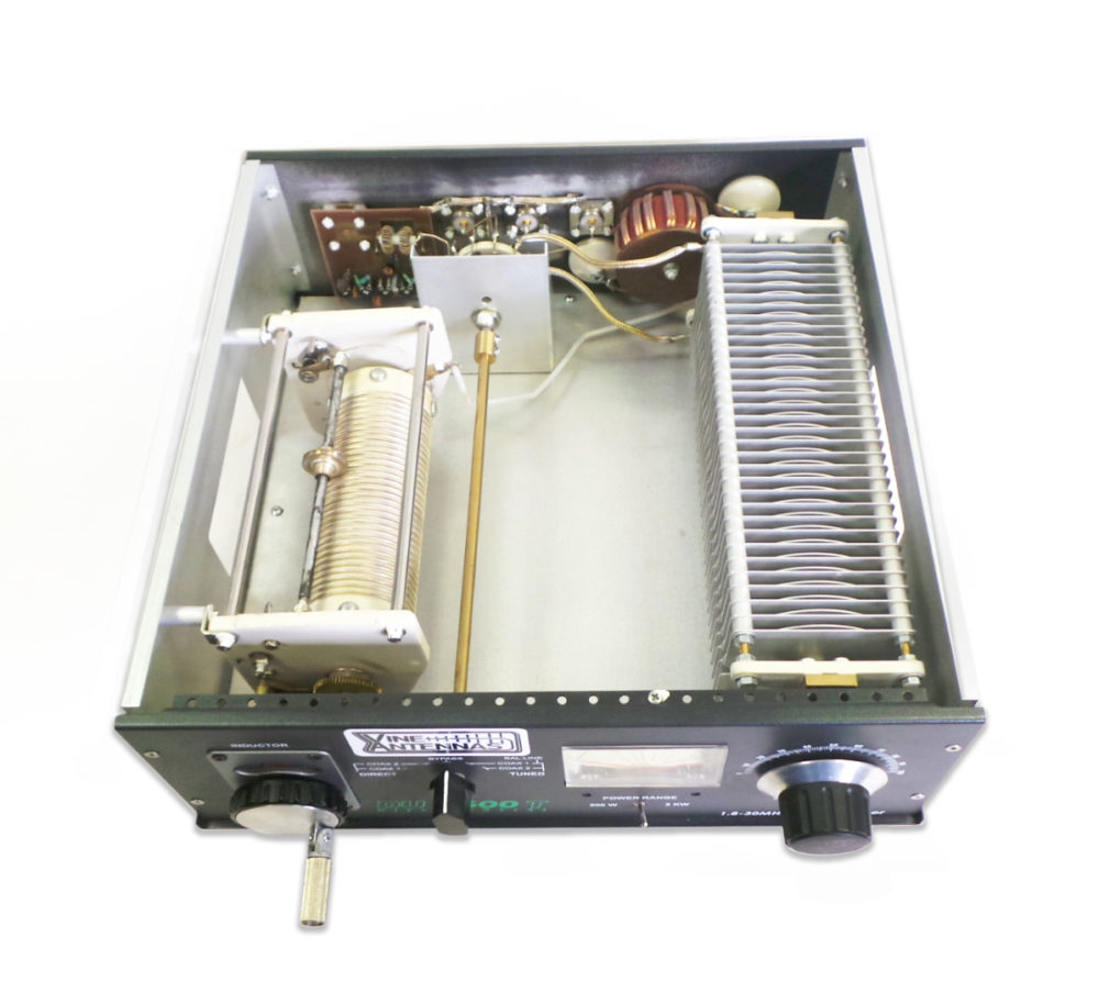 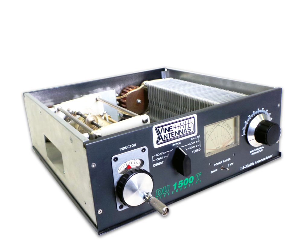 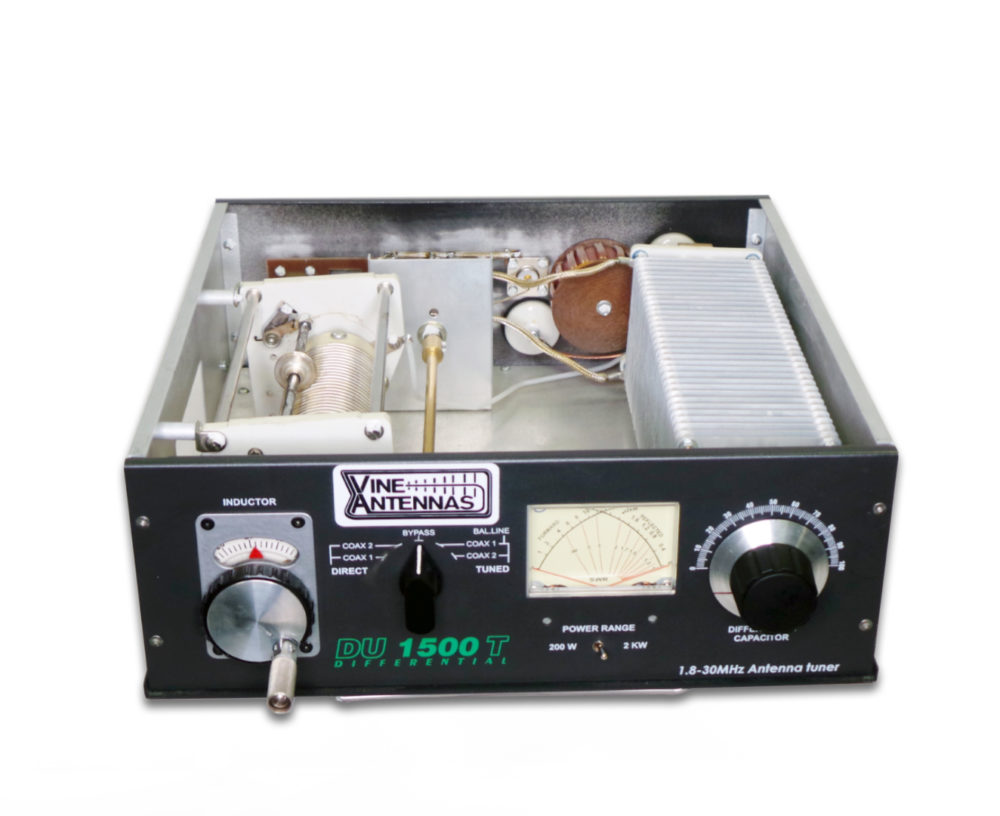 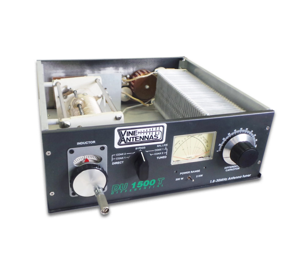
|


